RKS Ripple Control System

RKS System – Seamless Flexibility and Scalability

Open System Architecture

The RKS system can be adapted to any possible customer requirements. It can be configured either as a centralised system, with a stand-alone controller, or as a decentralised system, with a central controller controlling a number of local controllers. In addition, combinations of these configurations are also possible.

The following figures explain these configurations in detail.

It should be noted that when changing from one configuration to the other, no hardware changes are required: simply an upgrade to the firmware in the controllers is necessary. Licensing costs may differ however.

Modern Communication

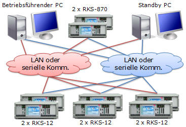
In general, RKS control units can be networked via a local area network (LAN).  In this case, communication takes place via an Ethernet connection, in accordance with TCP/IP, and uses either copper cables, fibre-optic cables or WLAN.

The LAN allows for:

  • Networking of multiple workstations in the control centre. Depending on the access rights, each workstation can be used either for parameterisation or operation.
  • Data export to other systems (e.g. export of working hours to MS-EXCEL™ via an office-LAN).

Naturally, RKS control units can also be connected via conventional communication infrastructure such as V24 interfaces or a permanent cable connection.

Centralised Control (Stand-alone Controller)

Rundsteuerung Kommandogeräte, RKS System, Zentrales KommandogerätRundsteuerung Kommandogeräte, RKS System, Zentrales Kommandogerät

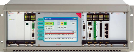
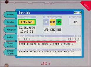
The RKS-16 central controller autonomously controls the operation of the ripple control system, independently of its connection with the PC. It can be operated from the PC or, optionally, via the built-in LCD touch screen. Parameterisation and setting of protocols takes place via the PC. The central controller can control up to 128 sets of injection equipment by means of direct impulse telegram transmission.

It is also possible to operate and parameterise multiple RKS-16 central controllers from a single PC. This is particularly useful when the time programs for all RKS-16 central controllers are identical, but when individual load controllers are used for each RKS-16.


Decentralised Control System

Rundsteuerung Kommandogeräte, RKS System, Dezentrales Kommandosystem

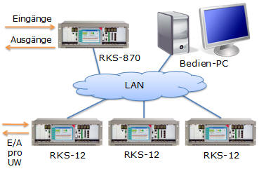
In a decentralised architecture the RKS-870 central controller takes over responsibility for system control and coordination of the RKS-12 local controllers. In case of a communication loss, the local RKS-12 controllers automatically take over control of the injection equipment.

The system can optionally also be operated without a central gateway. The RKS-870 central controller has the advantage that it is a robust hardware solution, specially designed for ripple control applications. The PC is always used for the operation, parameterisation and setting of protocols.

The RKS-870 system offers a special advantage since it can accommodate mixed systems.  This is especially useful for transition phases, as the central controller can also control ripple control injection equipment units using the direct impulsing control method.

When using an automatic load controller, power measurement values from the various RKS-12 local controllers can be summated in the central controller.

Redundancy Strategies

A decentralised system makes use of vertical redundancy where, in case of a communication line failure or a master control component failure, the local RKS-12 control unit affected by the failure takes over autonomous control of its associated ripple control injection equipment.

Redundancy and availability of the system can be increased by central and local horizontal redundancy.

Rundsteuerung Kommandogeräte, RKS System, Redundanzstrategien„Central redundancy“ means a redundant central control double-PC system and, where applicable, doubling the FWK-870. This guarantees a complete backup in case of a central system failure.

„Local redundancy“ means doubling all local controllers so that a potential failure of a single RKS-12 will not interfere with the other ripple-control operations.

RKS-PC-Software

User Friendliness and Customisation

Kommandogeräte, RKS System-Software, Benutzerfreundlichkeit und kundenspezifische AnpassungenThe RKS-software is based on many years of experience in the Ripple Control field. The various menu screens and functions, which have been specially designed for various ripple control functions, can be operated intuitively. Special customer requirements can be met easily.

Just a Click away

The ”Objects” tab gives an overview of the current state of all objects.  The selected object can be manually switched by right-clicking. In addition, object-specific data from other tabs (e.g. time program, archive, programming of a specific command) can be easily accessed from this screen.

The tab ”Control Unit” shows the current status of all control units connected with the system. All control units can be supervised, operated and updated from this screen.

Message Signalling and Archiving

Error and warning messages can be triggered from various sources within a ripple control process. For each possible message, its behaviour can be defined in detail.

Each message can be:

  • Registered in the Archive.
  • Visualised in the Alarm screen with one of three priorities. Depending on the message’s priority, various acoustic signals can be triggered via an internal soundboard. All current messages are listed in the Alarm screen.
  • Transmitted to a central alarm system via an alarm output contact.

A record of all operation-relevant incidents is stored on the hard disk of the PC. The History screen with its search and filter mechanisms is a very powerful tool for long-term evaluations of likely error sources in ripple control operation.

Kommandogeräte, RKS System-Software, Meldesignalisierung und Archiv

An automated backup of the Archive and the Database is possible on a USB memory-stick, an external hard disk or a network drive.

All programming and parameterisation of the ripple-control units and commands can be entered in the Administration screen. Access to this screen can be protected with a password.

In order to reduce manual maintenance of the database, RKS systems include the ability to automatically calculate movable holidays, which only need to be defined during the initial commissioning.

Measured Values

Kommandogeräte, RKS System-Software, Messwerte

Time-dependent load curve display, showing the comparison between two days

The following values of each local controller can be displayed in the Measured Values screen:

  • Transmission graphics: Real-time measured pulse pattern of uploaded transmissions. This graphic is very helpful when analyzing pulse errors indicated by the check-back receiver TRE-1.
  • Start pulse levels: Quick and very useful overview of all start pulse levels recorded by the TRE-1 check-back receiver. This helps in analyzing possible problems related to signal strength, e.g. a defective coupling capacitor.
  • Temperature and luminance: Temperature and luminance values that are sensed in the antenna of the GPS-1 receiver.
  • Regulator archive (see screen shot): In addition to the load curve, the target and the switching of the commands is shown. Load curves from different days can be compared.
  • Load peaks: Calculates a definable number of load peaks during a definable time span.
  • Operating hours (option): Calculates the operating hours of defined commands: daily, monthly and yearly calculations are available.

All graphical charts can be zoomed and horizontally and vertically moved.

Safe Operation of Public Light Switching

The RKS software provides various means to make the switching of streetlights and public lighting safer. To avoid unintended initiations of streetlight and public lighting commands, the signals from the photocell can be verified by the software-internal astronomic calendar.

Kommandogeräte, RKS System-Software, Sichere Schaltung der Strassenbeleuchtung

The times of sunrise and sunset are calculated automatically based on the geographical coordinates entered into the system at the time of commissioning. Coupled with preset time windows either side of the calculated switching times, this prevents incorrect switching On or Off caused by a possible faulty photocell.

In a system with more than one local controller, the software offers the possibility of forming groups with the same switching times (e.g. when the photocells in 2 out of 5 substations are On, then the switch On command is executed for the whole group). In case of a failure of the transmission lines, the local controllers will switch autonomously according to the local photocell signal.

Software Options

Kommandogeräte, RKS System, Software-OptionenOverview page of the load controller

Load Control

The Load Regulator screen shows the state of the load regulator. It gives an overview of all objects controlled by the load regulator as well as the current demand.

The screen lets the user make manual changes to the state of the controlled objects.

All parameters of the control algorithm and the object groups are recorded in the Administration screen. In addition, a switch-on duration (or duty cycle) supervision can be programmed for each control group, which ensures that the boiler or geyser is switched on for a minimum time, or is charged up afterwards. Various alarms and messages ensure that the operator is kept informed of the condition of the automatic load controller.

Target values can be entered as required either as individual values or in accordance with a daily profile. Even here, the behaviour of the software can be individually set with respect to messages and reactions on reaching the target value.

SCADA Interface

For integration with a SCADA system, the RKS software can export Excel-type *.csv files, listing every address being used. Typically this file can be imported into the SCADA software where only the link to the ripple controllers has to be chosen.

Alternatively, if these conditions are unable to be fulfilled, separate software exists for the local and central controllers to bring different addresses and configurations of IEC-protocols together. Despite the additional parameterisation work and possible error sources, this provides a method to connect various systems together.

Operating Time Meter

The operating time meter records and sums up the duration in which the respective ripple control object is activated (i.e. in the ON position). This function can be useful either for invoicing or for statistics.

The stored operating times can be summed up daily, monthly or annually.

The RKS-870 system also makes use of the vertical redundancy of the decentralised technology. Should the main unit fail the data will be recorded by the RKS-12 local controllers. As soon as the main unit is operational again the missing operating times during the failure will be copied from the local controllers.

User Administration

In the User Administration, individual user rights can be defined for every user.

Powerful and robust Hardware

Kommandogeräte, RKS System, Leistungsfähige und robuste Hardware

With the RKS family of controllers, Swistec offers a proven ripple control solution. Thanks to its highly flexible architecture, it can be integrated into all ripple control systems.

Our reference list covers systems from one up to over 100 transmitters. State-of-the-art hardware and software architecture leads to a flexibility that also supports unique system configurations.

All hardware components are designed for use in a harsh industrial environment and have no moving parts (no fans or hard disc drives etc.) which ensure a maximum service life.

The modular concept permits on the one hand an easy addition of further components and on the other hand a quick change-out of individual components in the event of a failure.

Basic Execution

  • The RKS offers the following communication interfaces: TCP/IP, V24, current loops, VF channels, as well as dial-up and leased line connections via copper cable, phone line or GSM.
  • Support for all ripple control protocols and ripple control transmitters. Decentralised systems can manage and transmit various protocols in parallel.
  • When operating in remote control mode, secured data is transmitted via standardised SCADA protocols such as IEC 60870-5-101 (serial communication) or IEC 60870-5-104 (network communication).
  • Powerful processor systems with generous memory extensions allow for a complete storage of all variable schedules and extensive operation protocols.
  • Parameterisation and operation of the unit via the modern RKS software direct or by means of a notebook connected to the serial RS232 port of the unit.
  • Optionally, the unit can be operated via a built-in LCD touch-screen display ISC-1. Necessary tasks can be quickly, easily and reliably conducted in local-control mode.
  • Three different power supply modules for the following supply voltages:
    – 95-265 VAC / 130-370 VDC (TES-43)
    – 105-230 VDC (TES-43/105)
    – 48-72 VDC (TES-43/60).
  • EMV-tested and CE-certified in accordance with IEC 1000-4-xx
  • Interfaces on the processor module: LAN, COM, USB, SD-card slot for SD-cards up to 1 GB, analogue input 0…20 mA for the load regulator.
  • Also available as a portable unit.

Options for the RKS Hardware

LCD Touch-screen Display ISC-1

The ISC-1 with its easy-to-use touch-sensitive colour display offers a clear overview over local ripple control processes, all without the need to connect a notebook.

Kommandogeräte, RKS System, Erweiterungen der RKS-Hardware

The six hotkeys to the left of the display guarantee a quick access to all ripple-control issues:

Status Displays the current operation status
Commands Fast, structured access to all ripple-control commands for manual transmissions
Timetable Displays the timetable that has been stored in the RKS-12
History Displays the operation protocol and stores errors
Measured Values
Displays current measured values of ripple control processes and of the optional GPS-receiver.
Setup Einstellungen des Kommandogeräts, einschließlich des optionalen GPS-Empfängers (GPS-1 von Swistec oder GPS-167SV von Meinberg). As a consequence, lower-cost GPS-receivers without display can be used so that the investment into an ISC-1 pays off very quickly.
GPS-Receiver GPS-1

Ripple control operations in intermeshed networks require phase-synchronous injection at each injection point. This is preferably achieved by the use of a phase-locked pilot frequency, which nowadays is generated by a GPS receiver.

Kommandogeräte, RKS System-Hardware, GPS-Empfänger GPS-1

The GPS-1 receiver from Swistec provides the following important benefits, in addition to generating the pilot frequency and time signals:

  • Photocell integrated in the external antenna in order to derive the switching signal for the control of the streetlights
  • Temperature sensor integrated in the external antenna in order to calculate charging times for night-time charge storage heaters

A big advantage of integrating all measured values into one system lies in the simple installation procedure. All information is transferred via a single 50 ohm coaxial cable, type RG-58.

Check-back Receiver TRE-1

The check-back receiver TRE-1 for ripple control signals provides an active and continuous supervision of the audio frequency signal level appearing on the busbars at the injection point.

In addition, the TRE-1 monitors the presence of harmonics, and provides automatic support of injection into two and more busbars, as well as the remote supervision of audio frequency signal levels via the GSM network.

The TRE-1 provides two independent three-phase inputs that are suitable for a voltage range from 57 VAC to 400 VAC. The input selection can be adapted dynamically. Should a transmitter feed into more than two busbars, multiple TRE-1 units can be cascaded.

  • Fully integrated into the RKS environment
  • De-coding of all ripple control telegram types
  • 3-phase current and voltage measurement
  • Configuration of different filters for all frequencies up to 2 kHz